Contact us
Firmware Development Flow
In this post we will dive deeper into the development flow on the firmware side.
Quick overview of firmware design
Firmware design is not so popular out there like for example software design or even hardware design. It is even hard to find great material in this topic. However, in the embedded systems world it has a superb relevance when you are doing professional work. In modern days, coding is a highly valuable but not critical skill when you are imaging products for the real world.The increasingly powerful AI tools are making programming a by-product instead of the core of new businesses. But the design thinking, the system approach and the capability to understand real problems and imagine structured solutions are and will be extremely relevant in our field.
In this line, firmware design has to deal more with architecture and system design than with programming itself. Of course you need to know programming languages, compiler mechanics, and even software-hardware interaction to be able to design effective firmware. But the skill set is quite different for both types of work. On the web you can find a tutorial for nearly every coding challenge or task you can face on your daily work. Also with automation and copilot tools the programming act by definition is more likely to be automated. The real value is not in knowing about syntaxes to write for, while and if in every programming language, but instead knowing what has to be done to solve the problem underneath the code. And this is where firmware design comes into the scene. If you have the ability to think in detail about how a real problem can be solved using code for embedded systems, then the code implementation goes to a second plane.
That’s why senior developers and experienced engineers focus more on architecture, diagrams and documentation instead of the nitty-gritty of code implementation. In today’s world, the importance of clean architecture and firmware design is more relevant than never before, because complete messes caused by unguided AI tools are everywhere. The difference between a successful product and an unmaintainable messy development comes from the design, before the first line of code is written. When you are working on a new product, ask first about resource constraints, speed requirements, error handling, robustness for safety, processor architecture to be used, bare metal vs RTOS, and so on. These topics will guide you into a structured development instead of jumping right away into low level implementation details.
We are convinced that professional firmware development starts with an organized process to handle every stage of the project in a confident and structured way. We hope to shed some light to this topic in this blog.
The eming.co process
On eming.co we focus on firmware design to make co-development with the hardware side a successful story. That´s why we use the circular process with 4 main stages: Specification, Design, Implementation and Validation. These macro stages are detailed as shown below.
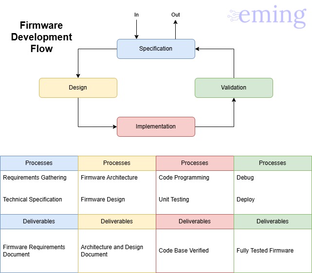
This graph shows the processes and deliverables of each step in the flow. Our methodology is based on today’s world of rapid integration and powerful capabilities with short market times. The presented flow is concise and scalable to different scopes and scales. The flow is the same for each particular piece of firmware at any level of development and some of the processes are iterative like for example the Code Programming – Unit Testing and the Debug – Deploy cycles. This methodology is compatible with agile principles applied to the embedded systems world.
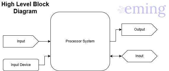
Particularly, for firmware design we work with 3 diagrams that help to translate requirements and constraints into implementable modules and functions. These diagrams are: High level block diagram, Software module diagram, and Hierarchy layered diagram.
The High level block diagram can easily be the High Level Black Box diagram typically used on Hardware design if it is detailed enough to understand all the hardware pieces, interconnections and devices that interact in the system. At this point, we do not know how all of these pieces will interact together in the system application.
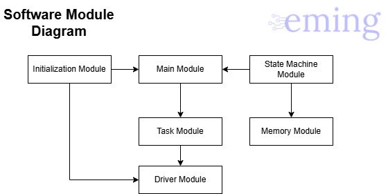
With this diagram in place, we can move on to the Software Module Diagram. This diagram has a deeper definition on how the devices will be “wired” in the application’s program and what modules need to be created to properly handle all of the hardware and software processes the system needs. Here is a good approach to use UML or other kinds of diagrams that help define modules, interfaces, properties information, modules dependencies, etc.
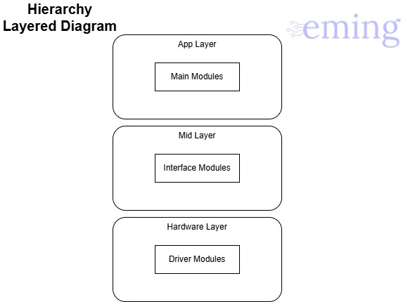
Finally, before moving into code implementation of the firmware design, the Hierarchy Layer Diagram should be done to evaluate how the program will be structured. On firmware development we are working very close to the hardware, and we do not want to have a whole program hardware-dependent. That is why we design this architecture diagram to clearly define the layers of the program and compartmentalize the software modules to make them reusable, truly modular, and independent between each other. This diagram gives us details about how the code will be implemented on each layer.
This firmware design process is iterative, as deeper details are needed, probably the structure needs to adjust to the new specifics. Once the design phase is frozen according to the company standards, the Implementation and further stages of the development can be started. With this methodology and flow we can take care of your project. We develop your custom firmware with professionalism and agility. Continue reading for more or contact us.